Metro Jet System
3.1 Measuring and Paying Out
According to the measurement reference point, use the total station to measure the pile position. Before the measurement and release, the measurement reference point, benchmarking point and the reference line of the building (structure) should be reviewed, and corresponding protective measures should be taken.
After the pile position measurement and release is completed, the surveyor will conduct self-inspection first. After the self-inspection is confirmed to be correct, report to the supervision engineer for acceptance. Only after the acceptance is qualified, construction is allowed, and the use of unaccepted piles is strictly prohibited. The plane error of pile position measurement and placement shall not be greater than 5 mm.
3.2 Digging trenches
Dig trenches along the axis according to the pile position measured and placed. After the trench excavation is completed, the pile position should be re-measured, and the site should be laid with steel plates according to the site conditions to ensure the safety of subsequent operations.
The width of the groove bottom is about 1~2m, and the depth is 1~3m.
3.3 Lead hole
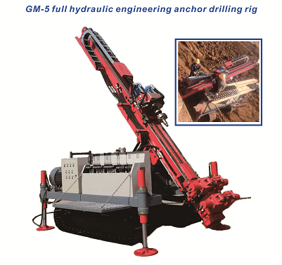
The drilling rig is equipped with a guide cutting bit for pre-drilling construction, and the diameter of the pilot hole is determined according to the diameter of the MJS pile.
The depth of the pilot hole should be greater than the designed hole depth by 1 mo. In order to ensure the verticality of the hole, after the pilot hole is completed, a sleeve drill is used to sweep the hole, and then the hole is cleaned, and the mud with a specific gravity of not less than 1.1 is poured to prevent the hole from collapsing.
3.4 Host in place
The foundation of the MJS host should be solid and flat. In order to prevent uneven settlement due to weak foundation during the construction process, channel steel or steel plates are erected at the bottom of the drilling rig to ensure the stability of the equipment during MJS construction.
Use a crane to hoist the MJS main machine in place, connect the main machine power supply, adjust the position and direction of the main machine, make the bottom center of the MJS drill bit align with the center of the casing, and extend the outriggers to level the main machine, and use square wood support pads to be firm.
3.5 Drill test spray
Hang the drill bit into the power head of the main engine, install the back suction air adapter, install the water tap, and make sure that the pipelines are unobstructed for test spraying.
Rotate the drill bit to move the nozzle to a suitable position (avoid crowds). The operator of the main engine informs the background operator through the walkie-talkie, and turns on the main air and the 200 pump in turn to test spraying to confirm whether the spraying of the drill bit is normal.
3.6 Lowering the drill pipe
Use the main engine power head to lower the MJS drill bit and drill pipe. During this time, the crane cooperates with the splicing drill pipe, connects the drill bit and the pressure monitoring display in the ground, and confirms that it is cleared when the drill bit has no load. When docking the drill pipe and drill bit, carefully check the condition of the sealing ring to see if it is missing or damaged, and whether the pressure in the ground is normal.
Lower the drilling tool to the pile bottom level. In the process of lengthening each section of drill pipe, connect the internal pressure data line accordingly.
3.7 Jet grouting
After the drill bit reaches the predetermined depth, start zero calibration, so that the “0” scale of the power head, the nozzle, and the white line on the drill pipe are in the same straight line, and then set various process parameters, including swing angle, pulling speed, number of revolutions, etc.
Turn on the backflow and backdraft first. When it is confirmed that the slurry discharge is normal, open the sludge discharge valve, turn on the high-pressure cement pump and the main air compressor. First, water was sprayed upward for 50 cm with a pressure of 10 MPa, and then the water was switched to cement slurry. After the drill pipe was lowered into place again, the upward spraying and grouting began.
During the spraying process, pay close attention to the pressure in the ground and the discharge of mud, and actively control the size of the sludge discharge valve to ensure that the pressure in the ground is within the specified value.
3.8 Removing the drill pipe
When it is necessary to disassemble the drill pipe, switch the cement slurry to water about 30 s before the end of the injection of the drill pipe; when the pressure of the 200 pump drops significantly, turn off the 200 pump, stop stepping and shaking, and close the discharge Mud valve. Then notify the background personnel in turn to turn off the grouting pump, cutting water pump and air compressor, remove the water tap and spray the completed drill pipe.
Note that in the process of disassembling the drill pipe, carefully check the condition of the sealing ring and data cable to see if it is damaged and whether the pressure in the ground is normal. If there is a problem, it should be eliminated in time. After dismantling the drill pipe, it is necessary to flush and maintain the drill pipe in time.
3.9 Move the machine into place
After the shotcrete reaches the designed pile top elevation and all drill pipes are removed, move the machine directly to the next hole position and carry out other construction methods.
3.10 Slurry treatment
The replacement waste pulp formed during the shotcrete process can be stored in a centralized location designated by the general contractor, and shipped out for processing after solidification.


